australia best dating appsgay dating your guide to finding lovewww ricoh usa comavengers infinity sweepstakesim a sick fuck i need 3 buckwhat is it call when you want to fuck a dadlooking for older women to fuck near megoogle doodle baseball wtfiowa sex dating daytonlesbian movie with teacher dating student
A motorcycle CDI unit circuit diagram is an essential tool for any motorcycle enthusiast or mechanic. It provides a detailed visual representation of the various components and connections in the circuit, allowing for easier troubleshooting and repair.
The CDI (Capacitor Discharge Ignition) unit is an important component in a motorcycles ignition system. It is responsible for generating the high voltage needed to ignite the fuel-air mixture in the engines combustion chamber. The CDI unit works by storing energy in a capacitor and then discharging it at precisely the right moment to create a spark.
Understanding the circuit diagram of a motorcycle CDI unit is crucial for diagnosing and fixing ignition system issues. It allows you to identify faulty components, check for continuity, and ensure proper connections. With a circuit diagram, you can trace the flow of electricity and pinpoint any potential problem areas.
A typical motorcycle CDI unit circuit diagram consists of several key components:
1. Stator: The stator is a stationary part of the motorcycles electrical system that generates the electrical power needed to run the motorcycle and charge the battery. It consists of a series of coils that produce alternating current (AC) when the engine is running.
2. Pick-up coil: The pick-up coil is a component that detects the position of the engines crankshaft and sends a signal to the CDI unit. This signal is used by the CDI unit to determine the correct timing for the ignition spark.
3. CDI unit: The CDI unit is the heart of the ignition system. It is responsible for storing energy in a capacitor and discharging it at the right moment to create a spark. The CDI unit also controls the timing of the spark and the advance or retardation of the ignition timing.
4. Ignition coil: The ignition coil is a transformer that steps up the voltage from the CDI unit to create a high voltage spark. It consists of a primary coil and a secondary coil, which are wound around a common core. The primary coil is connected to the CDI unit, while the secondary coil is connected to the spark plug.
5. Spark plug: The spark plug is the final component in the ignition system. It creates a spark that ignites the fuel-air mixture in the engines combustion chamber. The spark plug consists of a center electrode and a ground electrode, which are separated by a small gap. When the high voltage from the ignition coil is applied to the spark plug, it creates a spark across the gap.
The circuit diagram of a motorcycle CDI unit typically shows the connections between these components, as well as any additional components such as diodes, resistors, and capacitors. It also indicates the direction of current flow and any voltage or resistance values.
By studying the circuit diagram, you can identify potential issues such as broken wires, loose connections, or faulty components. For example, if you are not getting a spark at the spark plug, you can check the circuit diagram to see if there is a problem with the pick-up coil, CDI unit, or ignition coil.
Troubleshooting a motorcycles ignition system can be a complex task, but having a CDI unit circuit diagram can make it much easier. It allows you to systematically test each component and ensure that everything is functioning correctly. By following the circuit diagram and using a multimeter to measure voltages and resistances, you can quickly identify and fix any issues.
In conclusion, a motorcycle CDI unit circuit diagram is an invaluable tool for diagnosing and repairing ignition system problems. It provides a visual representation of the various components and connections in the circuit, allowing for easier troubleshooting. By understanding the circuit diagram and following the flow of electricity, you can identify and fix any issues with the CDI unit or other ignition system components. So, if you are a motorcycle enthusiast or mechanic, it is essential to have a motorcycle CDI unit circuit diagram on hand.
Universal Motorcycle CDI Circuit [Capacitor Discharge Ignition]. PCB Design A one-side PCB was developed for this universal motorcycle CDI circuit, but you may notice the components are attached on both sides of the board
australia best dating apps
. This was crucial because the circuit has to be kept about the same size as the existing CDI unit; 59 x 38 x 24 mm. If you review the picture of the prototype, this is clearer.. Bike cdi system explained
gay dating your guide to finding love
. CDI complete wiring and circuit details .
www ricoh usa com
. #CDI #ignition #bike #motorcycle dc cdi, cdi unit, cdi wiring, cdi circuit, cdi pin connections, cdi harness, cdi system, bike ignition system, motorcycle ignition system,.. CDI Wiring. How to wire a cdi, how to convert a bike to cdi, ignition .. Capacitor Discharge Ignition system. CDI is the most common ignition system in motorcycles and motorbikes motorcycle cdi unit circuit diagram. In this video I will show you how to wire a cdi in.
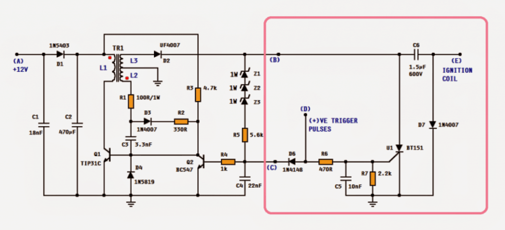
Make this DC CDI Circuit for Motorcycles - Homemade Circuit Projects. A DC-CDI is the one in which the high voltage (200-400VDC) is converted from 12V supply voltage. Researched and Submitted by: Abu-Hafss Studying the circuit, we see that it has two parts i.e. the CDI unit, enclosed in the pink box and the remaining circuit on the left is high voltage converter. The working of the CDI may be found in this article.. Simple Capacitive Discharge Ignition (CDI) Circuit motorcycle cdi unit circuit diagram. PCB Design CDI Circuit using an SCR, a few Resistors and Diodes Referring to the above capacitor discharge ignition circuit diagram, we see a simple configuration consisting of a few diodes, resistors, a SCR and a single high voltage capacitor. The input to the CDI unit is derived from two sources of the alternator.. What is CDI? What does a CDI box do? - RevZilla. The basic CDI system is a trigger mechanism, coils, and a box, often black, with capacitors and other circuitry inside. The trigger tells the box to fire, the box determines when to fire which coil with the capacitors, and zap goes the spark plug, ad infinitum.. Motorcycles CDIs Functions and How It Works - YaleTools. The CDI coil that gets a high voltage from the capacitor will cause electric sparks to spark in the plug
The higher the energy of the channeled capacitor, the stronger the spark in the plug to ignite the fuel. The function of the CDI ignition system is very important for the quality of the motorcycles work
avengers infinity sweepstakes
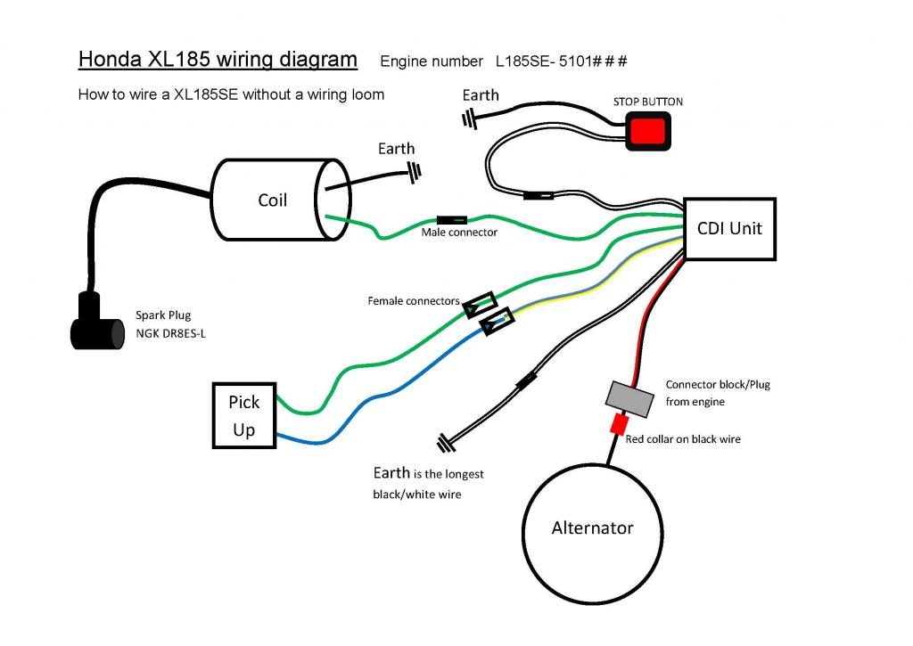
. This ignition system needs . motorcycle cdi unit circuit diagram. Motorbike Cdi Wiring Diagram. Picture. This is the ultimate guide to the motorcycle CDI unit. Check out our electrical wiring diagrams for the generic pin layout configuration of each. Motorbike CDI (Capacitive Discharge Ignition) basics. Have a look at the diagram. This is all youll ever need for your motorbike to run be it 2 stroke or four .. Cdi Circuit Diagram Motorcycle - Circuit Diagram. For motorcycle enthusiasts looking for an edge on the competition, CDI circuit diagrams are a must-have tool. Its easy to see why they are becoming increasingly popular among racers and hobbyists alike. With the right knowledge, you can unlock the true potential of your bike and become the envy of the track. Tbolt Usa Tech Database Llc. Motorcycle Cdi Unit Circuit Diagram - Circuit Diagram. Wire diagram cdi ignition a fast charging system for high sd engines make this dc circuit motorcycles homemade projects sportdevices programmable digital how motorcycle capacitor discharge works example circuits construction types working box rj 34 61 mvt direct dd 01 02 09 10 12 19 electronic 12v capacitive to test with multimeter 3 step guide .. How to Integrate a CDI Ignition with a mo.Unit - Revival Cycles. The easiest way to determine if you have a CDI is to look at your OEM wiring diagram and locate the kill switch. Once youve found it trace each wire leading away from it, there will likely just be two. One of them will go to the ignition module, the other wire will go to ground motorcycle cdi unit circuit diagram. The ground is the key, When the kill switch is activated it .. Motorcycle Cdi Unit Wiring Diagram - Circuit Diagram. Wiring loom light kill on off switch ignition coil cdi box spark plug kit for 110cc 120cc 125cc motorcycle atv dirtbike pit com 4 pin harness quad bike online at best s in srilanka daraz lk suzuki 1978 oem parts diagram unit partzilla universal dc igniter modified scooter moped buggy racing digital adjule programmable history review aliexpress er… Read More ». Motorcycle Cdi Unit Circuit Diagram - Headcontrolsystem motorcycle cdi unit circuit diagram. Erick Persija January 26, 2023 The Motorcycle Cdi Unit Circuit Diagram, ideas, and frequently asked questions are all readily available here motorcycle cdi unit circuit diagram
im a sick fuck i need 3 buck
. We produced this page for someone who looking for a Motorcycle Cdi Unit Circuit Diagram. A wiring diagram will show you where the cables should be linked, removing the requirement for guesswork.. Ignition Unit (TCI and CDI Systems) | Motorcycle Products | SHINDENGEN .. Products TCI (Transistor Controlled Igniter) System When the transistor is ON, current passes through the primary side of the ignition coil (coil hereinafter) from the battery to store the energy. motorcycle cdi unit circuit diagram. Motorcycle CDI Unit Circuit Diagram | EdrawMax Template. The motorcycle CDI unit circuit diagram consists of an exciter coil, ignition stop switch, diode, capacitor, ignition coil, resistor, gate, and trigger. The systems main purpose is to create the spark, which ignites an air mixture within the motorcycle engine.. CDI Capacitor Discharge Ignition Circuit Demo - YouTube. CDI Capacitor Discharge Ignition Circuit Demo. Motorcycle electrical circuit explained motorcycle cdi unit circuit diagram. Complete details of
what is it call when you want to fuck a dad
. - YouTube. Complete details of motorbike wiring system & CDI ignition system in this video you will learn all about motorcycle or motorbike electrical wiring and cdi ignition system motorcycle cdi unit circuit diagram. CDI is the.. Circuit Diagram Cdi Motorcycle - Circuit Diagram. How Motorcycle Capacitor Discharge Ignition Cdi Works Example Circuits. 4 Pin Cdi Box Ignition Coil Wiring Harness Kit For Quad Atv Dirt Pit Bike Go Kart 50cc 300cc Lifan motorcycle cdi unit circuit diagram. How To Wire A Motorcycle Basic Wiring Diagrams Motorcyclezombies Com
looking for older women to fuck near me
. Kill Switch On Xr Crf80 200 Thumpertalk. No Spark Issue How Not To Test The Cdi Unit Dr350s Rebuild .
2000 - cdi ignition circuit diagram. Text: principle of the digital capacitive discharge Ignition ( CDI ) system for two-wheelers, and outlines a , capacitive discharge method, known as Capacitive Discharge Ignition ( CDI ). This ignition system makes use , speeds, ignition must occur earlier in the compression stoke. motorcycle cdi unit circuit diagram
iowa sex dating dayton
. Electronic 12V DC Capacitive Discharge Ignition (CDI) Circuits motorcycle cdi unit circuit diagram. The whole concept for this electronic CDI can be understood by studying the shown circuit diagram below: The diodes, the SCR and the associated components form a standard CDI circuit. The high voltage of around 200V which needs to be fed to the above circuit is generated through an ordinary step down transformer connected the other way round.. How Motorcycle Capacitor Discharge Ignition CDI works | example Circuits motorcycle cdi unit circuit diagram. How it works. Look at the circuit diagram of CDI of C90 Honda motorcycle cdi unit circuit diagram. The flywheel rotates. Then the magnetic field cuts the charging coil core. It makes the AC voltage at that coil flows through D3 motorcycle cdi unit circuit diagram. It will rectify from AC into DC current to charge in both C1 and C2. Meanwhile, on the other side of the coil motorcycle cdi unit circuit diagram. The current will flow through R1 to D1 and .. CDI Circuit diagram | Motored Bikes | Motorized Bicycle Forum motorcycle cdi unit circuit diagram. 1 2 3 Next D Dood Surfston New Member Local time 3:51 AM Joined Oct 31, 2021 Messages 21 Jan 29, 2022 #1 Has anyone got a circuit diagram of the CDI unit that comes with 2-stroke kits? Im kinda curious how it works, as the CDI on a motorcycle usually has two voltage inputs, one a high voltage and the other for discharge timing. Greg58. Capacitor discharge ignition - Wikipedia motorcycle cdi unit circuit diagram
lesbian movie with teacher dating student
. Capacitor discharge ignition ( CDI) or thyristor ignition is a type of automotive electronic ignition system which is widely used in outboard motors, motorcycles, lawn mowers, chainsaws, small engines, turbine -powered aircraft, and some cars..